The Differences in North American and International CIPP Flexural Test Methods
Since the CIPP industry is now effectively a global supply chain, it’s useful to examine the differences between ASTM F1216 and ISO 11296 to determine how CIPP flexural properties measured by the North American testing method compares with flexural results determined by the international method.
There are many differences between ASTM F1216/F1743 and ISO 11296-4. These differences can be grouped into four broad categories: field sampling, test specimen, test orientation, span/test conditions.
Although ASTM D790 and ISO 178 substantially similar, there are important differences between the two methods.
Field Sampling
Determining the flexural properties of a CIPP installation is a destructive process. Ideally, a sample would be removed from the actual installation in an area of the pipe that best represents the conditions of the installation. This is done occasionally but requires that the sampled area be subsequently repaired.
To avoid this costly process, the accepted industry practice is to prepare a restrained sample with similar dimensions and heat sink properties in either a manhole or a termination. Once the installation is cured, the field sample is cut out and the remaining excess cured liner is trimmed flush to the existing pipe.
ASTM F1216 specifies that field samples for pipe sizes less than 18 inch should be cut from a restrained CIPP section removed from an intermediate manhole or a termination.
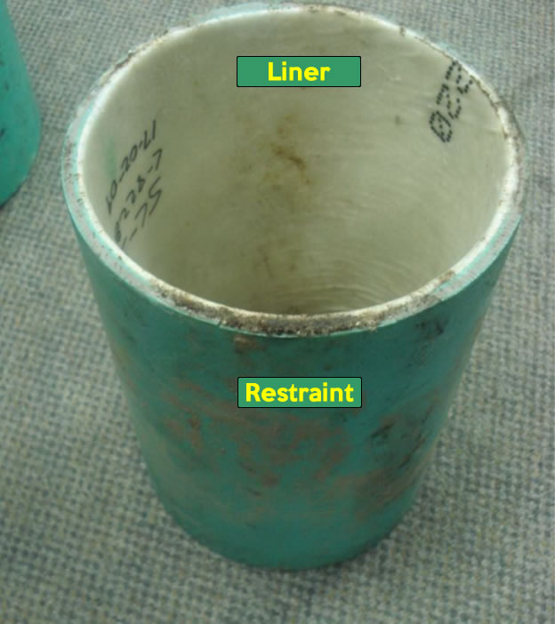
The restraint used is usually a sample of PVC pipe that closely matches the inside diameter of the installation (Figure 1).
For larger diameter pipes a flat plate type sample is clamped in a mold and placed in the downtube or silencer (Figure 2). Sandbags around the form are used to restrain the form and to simulate the heat sink present around the actual installation.
ASTM F1743 requirements for field samples are substantially similar to ASTM F1216. Flat plate type samples are used for fiber reinforced materials in ASTM F1743 to permit testing in both the longitudinal and circumferential directions.
A pipe section restraint is also used in ISO 11296 as a form to restrain field samples, but ISO 11296 defines more specific restraint conditions than the ASTM standards. ISO 11296 specifies that the form be made of clay or concrete pipe or a material with similar thermal characteristics.
Additionally, ISO 11296 requires of the temperature within the wet sand surrounding the form to be limited to 30°C maximum at a distance of 300 mm from the CIPP. All the samples which we tested for this study using the ISO 11296 method was restrained using the typical North American practice.
Test Specimen
Both ASTM F1216/F1743 specify that flexural properties be measured in accordance with ASTM D790. The specimen described in D790 is a simple beam with a square or rectangular cross-section. Typically five full-thickness rectangular test coupons are removed from the field sample such that the coupon axis is parallel to the pipe axis (Figure 2).
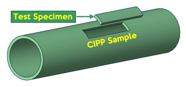
The dimensions of the flexural test coupon are described by ASTM D790 and depend upon the type and thickness of material that is being sampled (ie. sheet materials, laminated thermosetting materials…, molding materials and high strength reinforced composites, including highly orthotropic laminates).
D790 does not explicitly recognize the CIPP form of material, so the user of the method must decide which of the four material forms in the method most closely represents the CIPP material being tested.
ASTM F1216 does not provide guidance on test specimen selection so the user is free to choose from three different specimen types defined by ASTM D790, a) full thickness with existing interior and exterior surfaces, b) rectangular section with minimum exterior and interior material removal or c) 127 mm x 12.7 x 3.2 mm specimen (Figure 3). F1216 does not describe a method for measuring properties in the hoop direction.

The shaded portion represents the test specimen cross-section and its relation to the original wall thickness of the CIPP pipe.
ASTM F1743 addresses some of the test coupon ambiguities found in ASTM F1216 but it is still not entirely clear if the existing exterior and interior surfaces of the specimen are to be maintained. Section 8.1.3 states that “the full wall thickness of the CIPP samples shall be tested” however the next section 8.1.4 states: “Special consideration should be given to the preparation of flexural specimens to ensure that opposite sides are parallel and adjacent edges are perpendicular”.
F1743 also provides a method for measuring flexural properties in the hoop direction but only if the flat plate-type field sample is used.
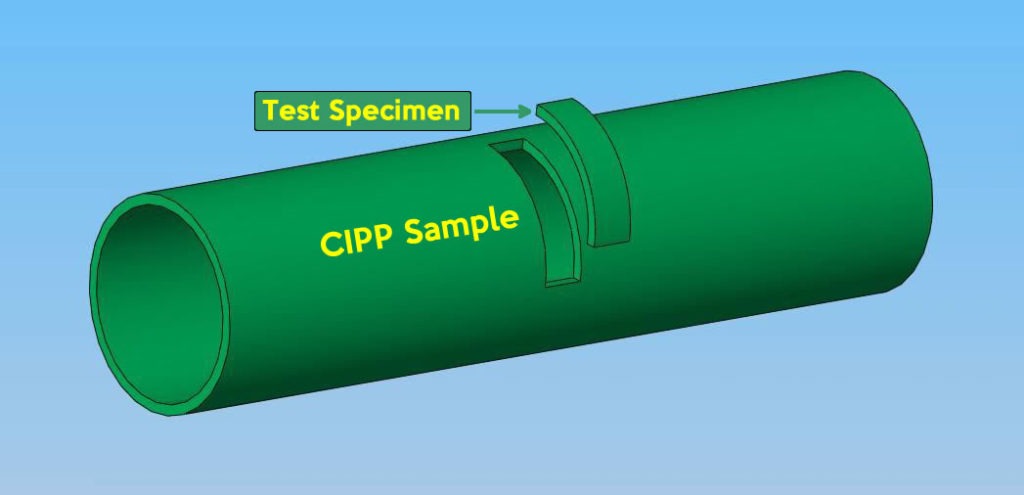
ISO 11296 describes testing in both the longitudinal and hoop directions. In the longitudinal direction, the method describes a full thickness section specimen with the existing outside and inside surfaces of the CIPP maintained (Figure 3, Type A). The hoop direction specimen is a transverse rectangular specimen that also retains the existing outside and inside surfaces of the CIPP as well as the curvature of the pipe wall (Figure 4).
Test Orientation
CIPP liners have been shown to exhibit loading direction dependent properties. Generally CIPP exhibits higher flexural properties when the inside diameter surface is loaded in tension. This loading condition represents the actual installed loading condition for non-pressure pipes.
ASTM F1216 does not provide guidance on test orientation. The user is free to test the coupons in either direction. ASTM F1743 specifies that the coupon be tested with the inside pipe face surface in tension. (ASTM F1743 does however reference ASTM D5813 for test specimen preparation.
The ASTM D5813 test method does require that the interior surface of the CIPP be placed in tension).
ISO 11296 specifies that the coupon be tested with the inside pipe face surface in tension.
Test Conditions
The test methods ASTM D790 and ISO 178 are substantially similar but there are some key differences in the test conditions based upon which standard is being used.
Span
All three standards specify the span for the test as a ratio of the depth of the test coupon. ASTM F1216 does not specify the span to be used for the test. The user must refer to ASTM D790 to determine the appropriate span to use for the test.
ASTM D790 defines the span as a function of the material type and configuration. The span to depth ratio can be anywhere between 14:1 (for sheet materials) to 60:1 (for highly anisotropic high strength composites).
ASTM D1743 specifies a 16:1 span to depth ratio.
ISO 11296 specifies a 16:1 span to depth ratio but permits the ratio to be decreased to 10:1 for smaller diameter and thicker walled liners (with the caution that lower span to depth ratios can result in underestimation of the flexural modulus and strength).
Speed of Testing
ASTM D790 contains two procedures, A and B. The default procedure, Procedure A, controls the speed of the test to a strain rate of 0.01mm/mm/min.
ASTM F1216 does not specify which procedure from ASTM D790 should be used. Therefore the default speed is 0.01mm/mm/min
ASTM D1743 specifies that Procedure A should be used (0.01mm/mm/min)
ISO 11296 specifies a speed of 10 mm/min.
Strain Limit
ASTM D790 terminates the test at 5% strain
ISO 178 does not define a strain limit for the test. Testing is continued until specimen failure.
Modulus Determination
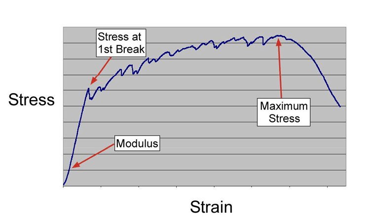
ASTM D790 determines the flexural modulus by drawing a tangent to the “steepest initial straight-line portion of the load deflection curve” (Figure 5).
ISO 11296 modifies the ISO 178 requirement determines the flexural modulus by determining the steepest slope of the stress/strain curve that is evident within the strain range 0.0005 and 0.0025 to 0.0005 and 0.006 (Figure 5).
Strength Determination
ASTM F1216 / ASTM D790 determine the flexural strength from the maximum flexural stress (Figure 5).
ISO 11296 / ISO 178 determine the flexural stress at first break (a different property than flexural strength) from the stress at the first discontinuity of the stress strain curve (Figure 5). ISO 178 also has a property “flexural strength” which determines the flexural strength from the maximum flexural stress in the same manner as the ASTM procedures. However, flexural strength is not a property used in ISO 11296.
Test Fixture
ASTM D790 has fixed position loading nose and supports (Figure 6).
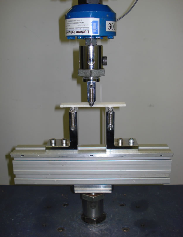
Both the loading nose and supports are fixed in their horizontal planes.
ISO 11296 requires that the loading nose be free to rotate in a plane perpendicular to the axis of the sample (Figure 7).
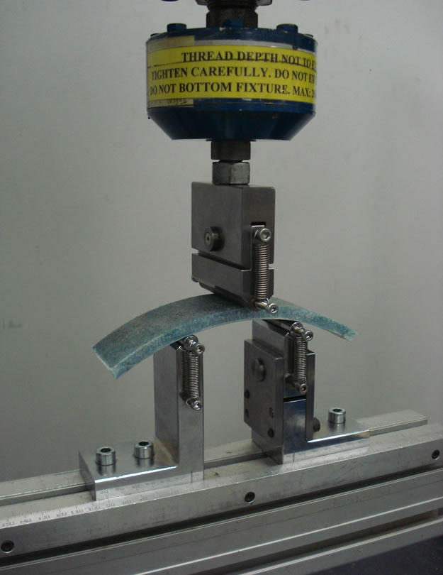
Both the loading nose and one support are free to rotate in their horizontal planes
Many of the CIPP systems being used in North America today were developed in Europe using ISO methods to determine flexural properties. The differences between the ASTM and ISO testing methods mean that data produced by the different procedures, while similar, cannot be directly related to the each other.
Get white papers, updates and event invites straight to your inbox, [nf-popup id=3809]
